
An antenna array refers to the arrangement and excitation of two or more antenna elements according to certain rules to form an array, thereby enabling electromagnetic waves to obtain a certain directionality when radiated in space.
Before discussing antenna arrays, it is necessary to first understand antenna groups and antenna elements. What is an antenna group?
The basic concepts involved in antenna composition include dipoles and antenna elements.
Dipole: When two symmetrical wires are opened and the distance increases, and the size of the entire conductor is equal to half the wavelength, the radio frequency induced on the conductor is in a resonant state, and the radiation efficiency of electromagnetic waves is highest at this time. This conductor is called a half wave oscillator, also known as a dipole, as shown in Figure 1.
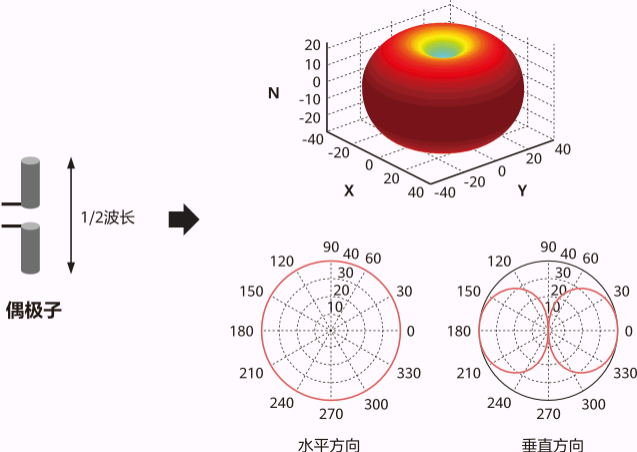
Figure 1 Schematic diagram of dipole
In 5G networks, for millimeter waves, the wavelength is at the millimeter level, so antennas can be made very small. In the same size of antenna panel, more antennas can be integrated compared to low frequencies.
Antenna element (also commonly known as antenna element): a dipole combined with a reflector plate forms a single antenna element, which can superimpose signals through reflection and achieve directional radiation.
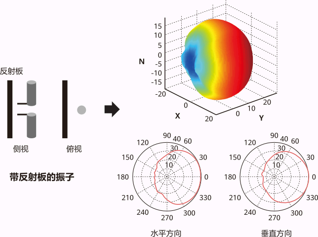
Figure 2 Schematic diagram of antenna oscillator
Next, let's introduce what an antenna array is.
A single antenna array is the basic component of an antenna, and when designing antenna feeds, multiple antenna arrays are usually arranged in an array as needed to form an antenna array. Antenna arrays can gather the energy of antenna elements to achieve greater gain.
Definition of antenna array gain: The ratio of the square of the field strength generated by the antenna array and antenna elements at the same point in space (i.e., the power ratio).
As shown in Figure 3, two antenna elements can form a beam. Under the condition of equal transmission power, the more antenna elements there are, the narrower the beam that can be formed, and the better the energy convergence effect.
The gain of an N-element array in the maximum radiation direction is Ga (dB)=10 lg (N).
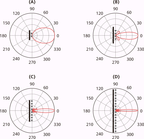
Figure 3 Schematic diagram of antenna array gain
When a wireless signal is transmitted from an antenna array over a certain distance to a receiving antenna, the phase of the received signal will change.
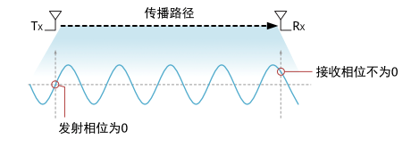
Figure 4 Schematic diagram of phase change during signal propagation
When the number of antenna elements is greater than 1, the signals emitted by different elements will have a superposition or cancellation effect at the receiving end due to phase differences. Here are two examples to illustrate:
Scenario 1: The same signal is sent out through two arrays, and when it reaches the receiving end, the phase is completely the same. At this time, the energy of the two signals is completely superimposed at the receiving end, and the combined energy is the maximum.

Figure 5 Schematic diagram of the superposition effect of two signals with the same phase at the receiving end
Scenario 2: The same signal is sent out through two arrays, and when it reaches the receiving end, the phases are completely opposite. At this time, the energy of the two signals is completely cancelled out at the receiving end, and the combined energy is 0.

Figure 6 Schematic diagram of cancellation effect caused by opposite phase of two signals at the receiving end
When using a single antenna, electromagnetic waves are emitted in all directions, and the signal radiation is an omnidirectional beam with a relatively close coverage distance. When electromagnetic waves formed by two or more antennas meet in space, they will superimpose or cancel to form new waveforms. When using two antennas, the signal radiation is a wide beam, and the coverage distance of the signal is farther than that of an omnidirectional beam. The more antennas there are, the narrower the beam of electromagnetic radiation and the farther the signal coverage distance. Large scale array antennas can further focus signals into narrow beams, resulting in longer coverage distances.
By adjusting the amplitude or phase of the signal on the RF link, the width and direction of the beam can be adjusted. This not only improves the energy efficiency of signal transmission, but also reduces mutual interference between different users and enhances system capacity. This process is called beamforming, also known as beamforming.
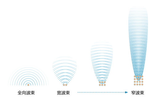
Figure 7 Schematic diagram of beamforming effect of antenna array
When designing and implementing, the phase and amplitude of the transmitted signal from each antenna array can be adjusted to converge the radiation beam in a specific direction, resulting in beamforming effect.
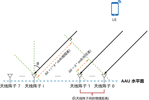
Figure 8 Schematic diagram of beamforming principle
As shown in the figure, for the signals received by the terminal from antenna arrays in the same horizontal row, there is a phase difference between different signal incident paths. By using the proportional relationship between wavelength and phase difference, we can determine the horizontal initial phase difference between each element of the antenna array through a formula.
After calculation, we have obtained the initial phase information of the antenna array, and by adjusting the phase and amplitude of the transmitted signals from each antenna array, we can achieve specific beamforming effects.
The gain types and functions of antenna arrays:
1. Array gain: Improve the downlink average signal-to-noise ratio; For array antennas, the signal received by the receiving end is the result of the superposition of signals from multiple antenna arrays. For noise N: Different antenna elements have uncorrelated noise, so the noise power remains unchanged after merging at the receiving end; For the useful signal S: the useful signals of different antenna arrays are correlated, so the signal power after combining at the receiving end is doubled; Therefore, using an antenna array and combining multiple antennas can obtain array gain, effectively improving the average signal-to-noise ratio (SNR).
2. Interference suppression gain: improves the average uplink signal-to-noise ratio; In multi antenna systems, using antenna interference cancellation algorithms such as IRC can effectively improve the Signal to Noise plus Interference Ratio (SINR) of the signal, bringing gain to the system in interference scenarios. For antenna arrays, the more antenna elements there are, the better the interference suppression capability.
3. Spatial diversity gain: reduces relative fluctuations in signal-to-noise ratio; The fading characteristics of wireless channels cause fluctuations in the received signal SNR. Random fading on a single path is inevitable, so multipath transmission will have diversity gain (each path is independent of each other and experiences independent fading; as long as the signal on one path is strong, reliable transmission can be maintained). The multipath transmission of signals from different antenna arrays can significantly reduce the probability of complete signal fading, thereby reducing the fluctuation of signal-to-noise ratio.
4. Space reuse gain: increases the number and capacity of transmission streams; At the transmitting end, antenna array technology is used to transmit more than one data stream in different antenna arrays, and the receiving end also has antenna arrays, forming a MIMO (Multi Input Multi Output) system. The more antennas, the narrower the beam, and the lower the correlation between beams, the more streams that can be spatially multiplexed.