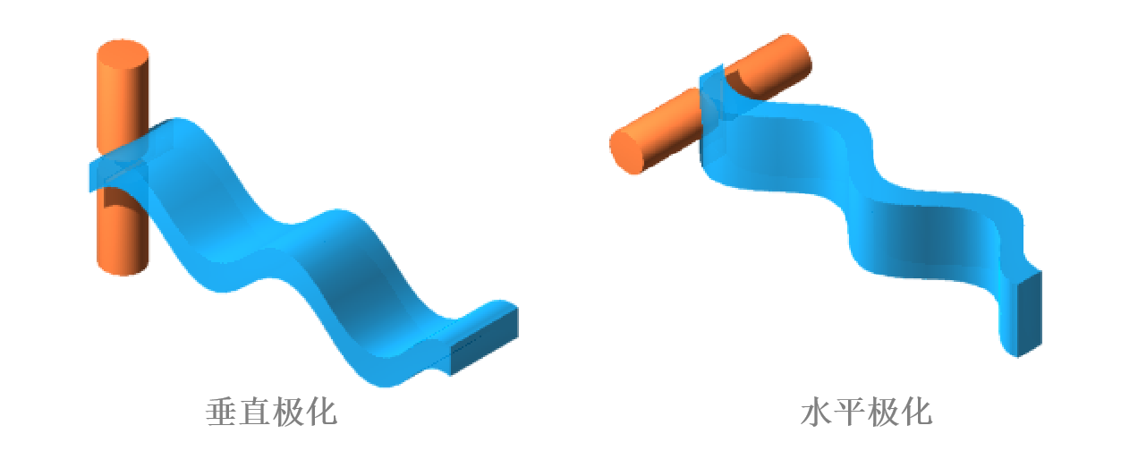
Antenna isolation is a key indicator for measuring the degree of mutual interference between signals of different polarizations, which reflects the energy leakage caused by different polarization modes during signal transmission.
In wireless communication systems, antennas are typically designed with orthogonal polarization to improve spectrum utilization, such as supporting both horizontal and vertical polarization simultaneously. However, due to limitations in antenna structure or environmental factors, signal energy fed to one polarization will inevitably couple into another polarization channel, and this non ideal signal crosstalk directly affects communication quality.

Taking a horizontally/vertically polarized MIMO antenna as an example, when a signal is input to the main polarization port (Port 1), the ratio of the power leaked to the cross polarization port (Port 2) to the input power of that port (expressed in dB) is the port isolation.
PS: "Isolation" usually refers to signal leakage between ports (such as two independent ports of a dual polarized antenna), and there is also a "polarization isolation" that focuses on signal suppression in the main polarization and cross polarization directions within the same port.
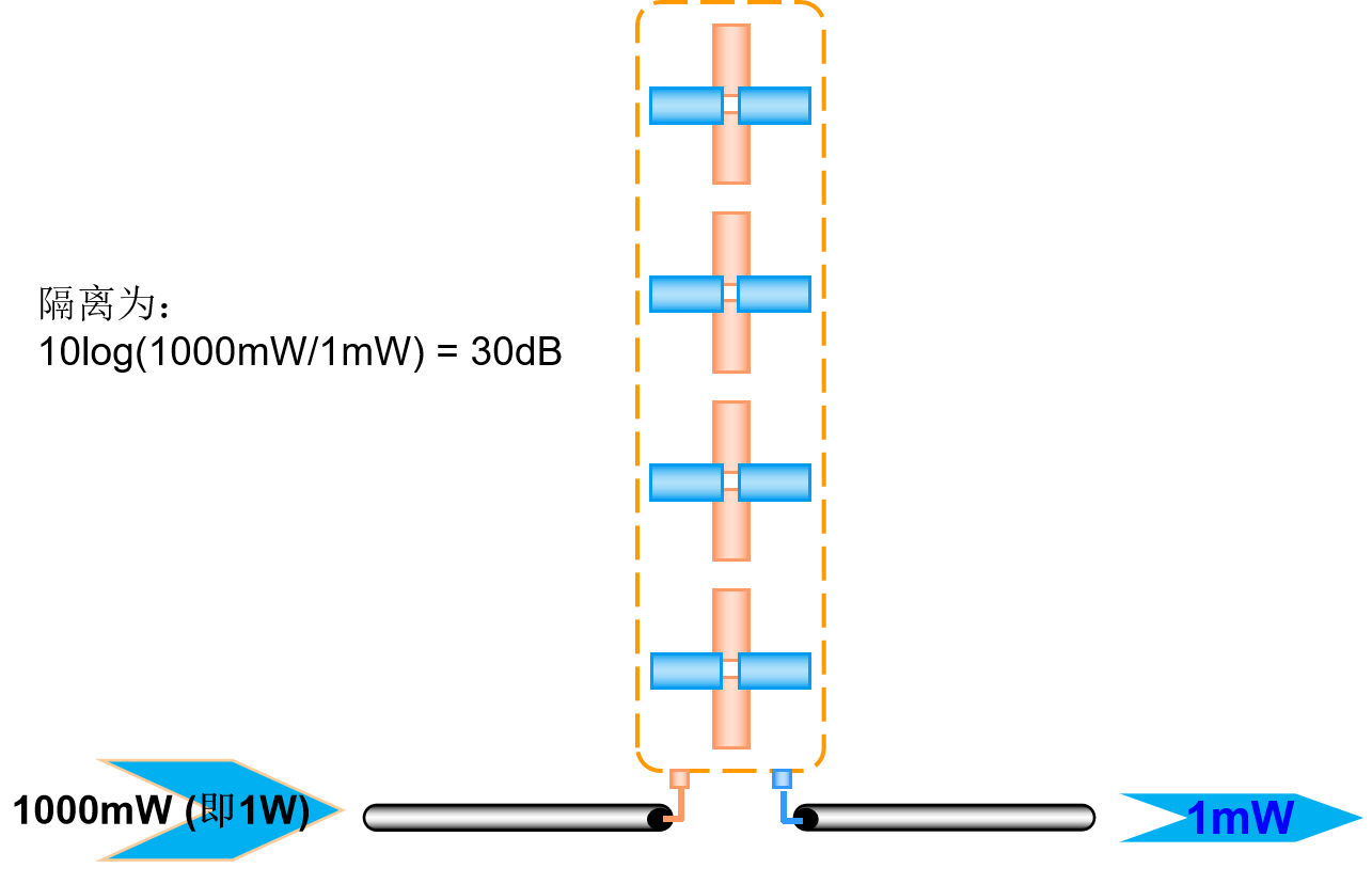
Taking the port isolation described in this article as an example, when a 1000 milliwatt signal is input to the main polarization port, if the leakage power measured at the cross polarization port is 1 milliwatt, the isolation can be expressed as 10log ₁₀ (1000/1)=30dB.

This logarithmic expression not only compresses a wide range of power ratios into manageable numerical ranges, but also more intuitively reflects the level of signal attenuation - every 10dB increase means that the leakage power is reduced to one tenth of its original value.
In engineering design, port isolation is mainly affected by the following factors: radiation element spacing: λ/2 spacing can suppress surface wave coupling and reduce energy penetration between ports; Grounding layer optimization: Reduce crosstalk caused by backside radiation through defect mode suppression (such as EBG structure); Decoupling structure: Load parasitic branches or neutral wires to directionally cancel out leakage signals.
Taking the satellite communication ground station antenna as an example, the horizontal/vertical port isolation can be increased to over 40dB through orthogonal mode couplers (OMT) and precision feed source networks, ensuring interference free transmission of uplink and downlink signals within the shared frequency band. In actual deployment, it is necessary to consider the deterioration of isolation caused by multipath reflection (such as a possible reduction of 10-15 dB in urban environments).